Notes Sections:
* Voice VLAN configuration mode command:
* QoS terms:
* Layer 2 QoS classification, handled by trunk protocols.
*
* Client Roaming:
- Switch Operation
- Switch Port Configuration
- VLANs and Trunks
- VLAN Trunking Protocol (VTP)
- Aggregation Switch Links
- Traditional STP
- Spanning-Tree Configuration
- Protecting the STP Topology
- Advanced STP
- Multilayer Switching
- Enterprise Campus Network Design
- Layer 3 High Availability
- IP Telephony
- Integrating Wireless LANs
- Securing Switch Access
- Securing with VLANs
Switch Operation. Section 1. Top
Switch Port Configuration Section 2. Top
VLANs and Trunks Section 3. Top
VLAN Trunking Protocol (VTP) Section 4. Top
Aggregation Switch Links Section 5. Top
Traditional STP Section 6. Top
Spanning-Tree Configuration Section 7. Top
Protecting the STP Topology Section 8. Top
Advanced STP Section 9. Top
Multilayer Switching Section 10. Top
Enterprise Campus Network Design Section 11. Top
Layer 3 High Availability Section 12. Top
IP Telephony Section 13. Top
* Two methods to provide Power-over-Ethernet (PoE) to connected devices:- Cisco Inline Power (ILP).- Proprietary, developed by Cisco before IEEE's.
- IEEE 802.3af.- Standard based method.
- Switch tries both methods:
- IEEE 802.3af.- Supplies small voltage and measure resistance. A reading of 25 Kohm indicates a PoE device is detected; 5 power classes are available, depending on resistance reading. (p.307)
- Cisco Inline Power (ILP).- Sends out a 340 KHz test tone; an ILP capable device will loop the tone back to the switch, thus if the switch hears the tone back, a capable device is detected.
- Pins used (RJ-45):
- Cisco Inline Power: pins 1,2 & 3,6
- IEEE 802.3af: pins 1,2 & 3,6 OR pins 4,5 & 7,8
     SW1(config-if)# power inline ...
     SW1# show power inline
     SW1# debug ilpower controller
     SW1# debug cdp packets
* Voice VLANs, connection between switch and IP phone can be trunk or access (no PC).* Voice VLAN configuration mode command:
SW1(config-if)# switchport voice vlan {vvlan-id|dot1p|untagged|none}
*Quality of Service (QoS).- It's the overall method used in a network to protect and prioritize time-critical or important traffic.* QoS terms:
- Delay (latency).- Time that takes a packet to travel from source to destination.
- Jitter.- Variations can occur in the amount of delay so that packets do not arrive at predictable times. Variations in delay is called jitter, eg. audio streams suffereing jitter will make the resulting speech or music sound choppy.
- Loss.- Packets lost in transit.
- IntServ (Integrated Service Model).- Requires advaced path reservation.
- DiffServ (Differentiated Service Model).- Does not need prior path reservation, QoS is dynamic, decisions are based in packet header info. Each switch and router inspect's each packet's header to decide how to go about forwarding that packet.
* Layer 2 QoS classification, handled by trunk protocols.
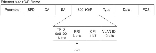
- 802.1q.-Each frame is tagged with a 12-bit VLAN id and a user field. The user field contains three 802.1p priority bits that indicate the frame CoS (class of service), 1-7 (seven is highest priority delivery). Native VLAN frames are not tagged, so they receive a default service configured in the receiving switch:

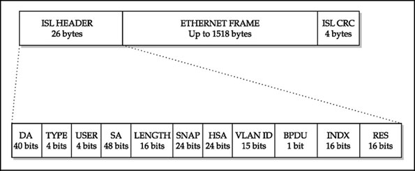
- ISL.- Each frame is tagged with a 15-bit VLAN id; and a 4-bit User Field, the lower 3 bits are used as CoS value:

- Catalyst switches make CoS seamless between ISL and 802.1q .
- Type of Service
- Present in original IP packet by design.
- Byte is divided into 3-bit IP Precedence and 4-bit ToS
- Limited to 3-bit IP Precedence.
- DSCP
- Used by DiffServ.
- Uses same byte, now called DS (Differentiated Services).
- DS is 6 bits, thus offers more flexibility.
- Backward compatible with ToS' IP Precedence bits.
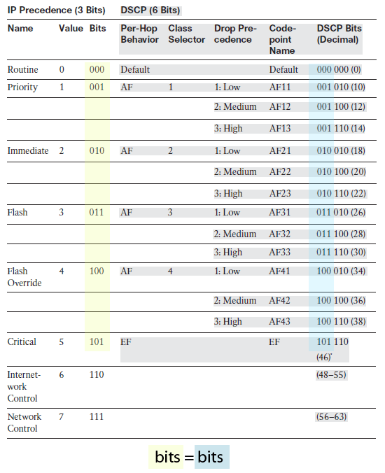
- IP precedence and DSCP fields mapping:

- Class 0: Default, offers only best-effort forwarding.
- Class 1-4: Called Assured Forwarding (AF) .
- Class 5: Called Expedited Forwarding (EF).
- Class 6: Called Internetwork Control. Set aside for network control traffic.
- Class 7: Called Network Control. Set aside for network control traffic.
- The higher the class the better service.
- Each DSCP class is further divided into 3 levels of drop precedence:
- Low (1)
- Medium (2)
- High (3)
- The lower the level the better service.
- Trust Boundary.- The permimeter formed by switches that do not trust incoming QoS information; usually, boundaries with another organization or service provider are not trusted, also QoS values produced by end users (eg. workstations) should not be trusted until verified. IP phones are trusted devices. Not trusted QoS values can be reassigned or overruled.
- Cisco IP phone QoS trust boundary configuration:
- Enable QoS on the switch (all ports are configured as untrusted by default).
SW1(config)# mls qos - Define the QoS parameter that will be trusted.
SW1(config-if)# mls qos trust {cos | ip-precedence | dscp} - Make the trust conditional.
SW1(config-if)# mls qos trust device cisco-phone - Instruct the IP phone how to extend the trust boundary.
SW1(config-if)# switchport priority extend {cos value | trust}
- Enable QoS on the switch (all ports are configured as untrusted by default).
- Switch uplinks (trunks) should be considered as trusted ports, as long as they connect to other trusted devices within trusted boundaries.
- Auto-QoS:
- Not meant for network core switches, use it in access layer switches (switches directly connected to IP phones/workstations).
- Configures a variety of parameters (commands): enabling QoS, CoS-to-DSCP mapping for QoS marking, ingress and egress queue tuning, strict priority queues for egress voice traffic, establishing an interface QoS trust boundary.
- Configuration. Select an interface at the QoS boundary and apply:
SW1(config-if)# auto qos voip {cisco-phone | cisco-softphone | trust}
- Not meant for network core switches, use it in access layer switches (switches directly connected to IP phones/workstations).
- QoS Voice verification commands:
     SW1# show mls qos interface interface
     SW1# show interface interface switchport //look for appliance trust(attached workstation)
Integrating Wireless LANs Section 14. Top
* Wireless Service Sets:- IBSS
- BSS
- ESS
- SSID-VLAN mapping: AP must be connected with a trunk to the switch.
- Supports Layer 2 roaming (multiple APs in same subnet).
- Other means must be added to support layer 3 roaming.
- All management is done in local AP.
- Lightweight AP.- An access point with a limited IOS meant to perform the 802.11 operation only.
- Lightweight APs become dependent on the WLC for every other WLAN function, such as: authenticating users, managing security policies, selecting RF channel and output power.
- APs management in centrilized in a WLC (Wireless LAN Controller):
- WLAN security
- WLAN deployment
- WLAN management
- WLAN control
- A lightweight AP binds itself to a WLC by using LWAPP or CAPWAP tunnel protocols:
- LWAPP (Lightweight Access Point Protocol).- Cisco proprietary, uses UDP ports 12222 and 12223 on the WLC end.
- CAPWAP (Control and Provisioning Wireless Access Points protocol).- Based in Cisco's; IETF standard (RFC 4118), uses UDP ports 5246 and 5247.
- Both protocols consist of two tunnels:
- Control messages tunnel.- Exchanges between the WLC and the LAP, used to configure the LAP and manage its operation. Messages are authenticated and ecrypted.
- Data tunnel.- Packets to and from wireless clients associated with the LAP. Packets are not authenticated nor encrypted.
- WLC specific functions:
- Dynamic channel assignment.- The WLC chooses and configures the RF channel used by each LAP based on other active access points in the area ( APs should use different frequencies to prevent interference with each other).
- Transmit power optimization.- The WLC sets the transmit power of each LAP based on the coverage area needed. Transmit power is also automatically adjusted periodically.
- Self-healing wireless coverage.- If an LAP radio dies, the coverage hole is "healed" by turning up the transmit power of surrounding LAPs automatically.
- Flexible client roaming.- Clients can roam at either Layer 2 or Layer 3 with very fast roaming times.
- Dynamic client load balancing.- If two or more LAPs are positioned to cover the same geopgraphic area, the WLC can associate clients with the least use LAP. This distributes the client load accross the LAPs.
- RF monitoring.- The WLC manages each LAP so that it scans channels to monitor the RF usage. By listening to a channel, the WLC can remotely gather information about RF interference, noise, signals from surrounding LAPs, and signals from rogue APs or ad-hoc clients.
- Security management.- The WLC can require wireless clients to obtain an IP address from a trusted DHCP server before allowing them to associate and access the WLAN.
- WLC platforms and capabilities:
- 2100.- 8 x 10/100 interfaces, handles up to 6,12 or 25 LAPs.
- 4402.- 2 x GbE interfaces, handles up to 12,25,50 or 50 LAPs.
- 4404.- 4 x GbE interfaces, handles up to 100 LAPs.
- 5500.- 8 x GbE interfaces, handles up to 250 LAPs.
- WiSM.- 4 GbE bundled in an Ether-Channel for each controller; Catalyst 6500 module with two WLCs, handles up to 300 LAPs (150 per controller), up to 5 WiSMs in a single chassis.
- WLC module for ISR routers.- Can be integrated in 2800 and 3800 routers, handles up to 25 LAPs.
- Catalyst 3750G integrated WLC.- Integrated in switch, handles 50 LAPs per switch, up to 200 LAPs per switch stack.
- Wireless Control System (WCS).- Optional server platform that can be used as a single GUI front-end to all the WLCs in a network.
- Cisco Wireless Location Appliance.- Tracks the location of thousands of wireless clients.
- LAP operation. LAPs are design to obtain all its configuration parameters from a WLC:
- The LAP obtains an IP address from a DHCP server.
- The LAP learns the IP addresses of any available WLCs (supplied by DHCP server using option 43, or by sending a broadcast).
- The LAP sends a join request to the first WLC in its list of addresses. If that one fails to answer, the next WLC is tried. When a WLC accepts the LAP, it sends a join reply back to the LAP, effectively binding the two devices.
- The WLC compares the LAP's code image release to the code release stored locally. If they differ, the LAP downloads the code image stored on the WLC and reboots itself.
- The WLC and LAP build a secure LWAPP or CAPWAP tunnel for management traffic and an LWAPP or CAPWAP tunnel (not secured) for wireless client data.
- An LAP is joined to 1 WLC at any time. However, an LAP can maintain a list of up to three WLCs.
- Traffic between wireless clients must go from LAP through the tunnel (LWAPP or CAPWAP) to the WLC back through the tunnel to the LAP and finally to the receiving wireless client.
- To extend VLANs to SSIDs the WLC must be connected to the local switch with a trunk; but connections fro the WLC to LAPs do not require trunks, in fact, the WLC and LAPs can be in a seperate isolated VLAN (see pic 15-11).
- Roaming in a Cisco Unified Wireless Network
- Intracontroller Roaming
same controller (only 1), same SSID, only same subnet
- Intercontroller Roaming
multiple controller, same SSID,same subnet OK, different subnet OK (Ether-IP tunnel, uses IP protocol 97),anchor point, foreign agent, - Mobility Groups
- Intracontroller Roaming
*
* Client Roaming:
- Layer 2 roaming:
- Layer 3 roaming: The client roams between APs located in different IP subnets. A tunnel is created.
Securing Switch Access Section 15. Top
Securing with VLANs Section 16. Top